Aviation Training Consultants: 800-874-5346

E6B Flight Computer Instructions

Resources > E6B Flight Computer Instructions

Click the button below each image to use a manual E6B flight computer online.

The Calculator Side of the E6B Flight Computer

  1. The calculator side consists of a stationary portion with a flat circular portion attached. The circular portion can be turned.


    1. The numbers along the outside of the stationary portion are referred to as the OUTER SCALE in this document.
      • The outer scale is used to represent distance, fuel, ground speed, true airspeed, or corrected (true) altitude, depending on the calculation being performed.
    1. The numbers on the edge of the rotating portion are referred to as the INNER SCALE in this document.
      • The inner scale is used to represent time, calibrated or indicated airspeed, and calibrated or indicated altitude, depending on the calculation being performed.
      • The number “60” on the inner scale has been replaced with a triangular-shaped arrow, referred to as the Index (e6b flight computer instructions).
        • This arrow is used as a reference to a rate, such as knots (nautical miles per hour) or gallons per hour.
    2. In the center of the rotating portion are three “holes” (windows) used to compute corrected (true) altitude, density altitude, and true airspeed.

    Scale Values

    1. The numbers on the outer and inner scales represent multiples of 10 of the values shown.
      • EXAMPLE: The number “20” on either scale may represent 0.2, 2.0, 20, 200, or 2,000.
    2. On both the outer and inner scales you will notice that the number of tick marks, or graduations, vary between numbers.
      •  EXAMPLES:
        1. The first tick mark to the right of “10” may represent 10.1, 101, 1,100, etc.
        2. The first tick mark to the right of “17” may represent 1.72, 17.2, 172, etc.
        3. The first tick mark to the right of “35” may represent 3.55, 35.5, etc. The second tick mark to the right of “35” may represent 3.6, 36, 360, etc.
    3. On the inner scale, minutes may be translated to hours and minutes by reference to the hour scale, which is below and inside the inner scale.
      • EXAMPLE: 120 min., or “12” on the inner scale is also 2 hr. as indicated by “2:00” below the “12.”
    4. On the hour scale, the tick marks represent either 5 min. or 10 min.
      • EXAMPLE: Between “1:50” and “2:00” the tick mark represents 5 min. Between “4:00” and “4:30” each tick mark represents 10 min.
      • The tick marks on the inner scale can be used to supplement the hour scale.

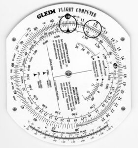
    The calculator side of the flight computer is constructed so that any relationship, or ratio, between a number on the outer scale and a number on the inner scale will remain constant for all other numbers on both scales.

    1. Rotate the inner circle so the “10” is opposite the “10” on the outer scale, and note that all the numbers around both circles are identical.
    2. Next, rotate “20” under “10” on the outer scale; now all numbers on the inner scale are double those on the outer scale.

Conversion of Nautical Miles to Statute Miles and Vice Versa

You can use the calculator side of your flight computer to convert nautical miles (NM) to statute miles (SM), or knots (kt.) to miles per hour (mph).

  1. Remember, the units you use must be equivalent, i.e., nautical miles and knots or statute miles and miles per hour.

On the outer scale at “66” there is an arrow labeled “NAUT” (nautical miles) and at “76” there is an arrow labeled “STAT” (statute miles).

  1. Example: Convert 100 mph to knots.
    • Rotate the inner scale so that 100, or “10,” on the inner scale is under the “STAT” index arrow.
    • Look at the “NAUT” index arrow on the outer scale to determine 87 kt. on the inner scale.

Use your flight computer to solve these practice problems (answers are located below).


  NM SM
1 107 ___
2 139 ___
3 ___ 181
4 ___ 78
5 320 ___

Answers to practice problems

    1. 123 SM
    2. 160 SM
    3. 157 NM
    4. 68 NM
    5. 368 SM

Speed, Distance, and Time Computations

Speed, distance, and time are three interrelated elements. With any two of these elements, you can compute the third (missing) element.

  1. The computations are
    • Speed = Distance / Time
    • Distance = Speed X Time
    • Time = Distance / Speed
  2. You can use your flight computer to make the above computations.
    • Note that in any problem both the speed and distance must be in either SM or NM.
    • You can convert SM to NM or vice versa easily as explained in the preceding module.

Determining Time Required

If you know the groundspeed and the distance, you can calculate the time. Time equals distance divided by groundspeed.

Example: How much time will it take to fly 120 NM at a groundspeed of 100 kt.?

    • Rotate the inner scale so the Index is opposite 100 kt., or “10,” on the outer scale, as shown in the figure.
    • Locate 120 NM, or “12,” on the outer scale.
    • Under 120 on the outer scale read 72 min. on the inner scale or 1:12 on the hour scale.

Use your flight computer to solve these practice problems (answers are located below).

 Groundspeed   Distance   Time
1. 80 kt. 300 NM _____
2. 95 kt. 19 NM _____
3. 105 kt. 62 NM _____
4. 120 mph 142 SM _____

Answers to practice problems

  1. 225 min. or 3 hr. 45 min.
  2. 12 min.
  3. 35.5 min.
  4. 71 min. or 1 hr. 11 min.

Determining Distance

If you know groundspeed and time, you can determine the distance. Distance equals groundspeed multiplied by time.

Example: How far will the airplane fly in 8 min. at a groundspeed of 90 kt.?

  • Rotate the inner scale so the Index is opposite 90, as shown in the figure.
  • Locate 8 on the inner scale.
  • Opposite 8 on the inner scale is 12 NM on the outer scale.

Use your flight computer to solve these practice problems (answers are located below).

Groundspeed Time Distance
a. 107 kt. 3 hr. 27 min. _____
b. 95 kt. 17 min. _____
c. 105 kt. 43 min. _____
d. 120 mph 1 hr. 24 min. _____

Answers to practice problems

  1. 370 NM
  2. 27 NM
  3. 75 NM
  4. 168 SM


Fuel Computations

You may compute either fuel used, fuel consumption rate, or time remaining using computations similar to those for speed, distance, and time.

The computations are

  • Fuel burned = Fuel consumption rate X Time
  • Time (available) = Fuel to burn / Fuel consumption rate
  • Fuel consumption rate = Fuel burned / Time

These computations are made on the flight computer in the same way as time and distance computations, except that gallons are used in place of miles.

Determining Amount of Fuel Used

If you know the fuel consumption rate and the time, you can determine the fuel used. Fuel used equals fuel consumption rate multiplied by time.

Example: How much fuel will be used during a flight of 2 hr. and 30 min. if the fuel consumption rate is 8.2 gallons per hour (GPH)?

  • Rotate the inner scale so the Index is opposite 8.2, or “82,” on the outer scale, as shown in the figure.
  • Locate 2:30 on the hour scale or 150 min. on the inner scale.
  • Opposite 150 is 20.5 gallons on the outer scale.

Use your flight computer to solve these practice problems (answers are located below).

  Consumption Rate     Time    Fuel Used
1.  17.0 GPH 1 hr. 10 min. _____________
2.   7.0 GPH 30 min. _____________
3.   10.2 GPH 2 hr. 5 min. _____________
4.   9.4 GPH 90 min. _____________

Answers to practice problems

  1. 19.8 gal.
  2. 3.5 gal.
  3. 21.2 gal.
  4. 14.1 gal.

Determining Endurance

If you know the fuel consumption rate and usable fuel on board the airplane, you can determine the endurance, or time, the airplane can fly. Endurance equals amount of fuel divided by the fuel consumption rate.

Example: If the fuel consumption rate is 10.3 GPH and there is 48 gallons of usable fuel, how long can the airplane fly?

  • Rotate the inner scale so the Index is opposite 10.3, as shown in the figure.
  • Locate 48 on the outer scale.
  • Opposite 48 on the inner scale is 280 min., or 4 hr. 40 min.

Use your flight computer to solve these practice problems (answers are located below).


Consumption Rate Usable Fuel Endurance (Time)
1. 16.3 GPH 62.0 gal. _____________
2.  8.2 GPH 24.5 gal. _____________
3. 10.6 GPH 50.0 gal. _____________
4.  9.0 GPH 38.0 gal. _____________

Answers to practice problems

  1. 3 hr. 48 min. or 228 min.
  2. 2 hr. 59 min. or 179 min.
  3. 4 hr. 43 min. or 283 min.
  4. 4 hr. 13 min. or 253 min.

Determining Fuel Consumption Rate

If you know the amount of fuel used and the time, you can determine the fuel consumption rate. Fuel consumption rate equals fuel burned divided by time.

Example: If an airplane used 15.4 gal. on a 1 hr. 25 min. flight, what was the fuel consumption rate in gallons per hour (GPH)?

  • Rotate the inner scale so that 1:25 on the hour scale, or 85 on the inner scale, is opposite 15.4 on the outer scale, as shown in the figure.
  • The fuel consumption rate is on the outer scale opposite the Index, which is 10.9 GPH.

Use your flight computer to solve these practice problems (answers are located below).

Time Fuel Used Consumption Rate
a. 145 min. 16 gal. ______
b. 54 min. 17 gal. ______
c. 1 hr. 15 min. 10.4 gal. ______
 
d. 3 hr. 40 min. 36 gal. ______

Answers to practice problems

  1. 6.6 GPH
  2. 18.9 GPH
  3. 8.3 GPH
  4. 9.8 GPH

True Airspeed and Density Altitude

Air density affects the indications of the airspeed indicator and the performance of the airplane.

Density altitude is the theoretical altitude in the standard atmosphere where the density is the same as the actual density you are experiencing in flight.

  • Density altitude is found by correcting pressure altitude for nonstandard temperature.
  • Pressure altitude can be determined by setting the airplane’s altimeter to 29.92 and then reading the altitude.
    • If this is done in flight, make a note of the altimeter setting before turning it to 29.92. After you determine the pressure altitude, reset the altimeter to the current setting.
  • The outside air temperature (OAT) can be determined by reading the current temperature on the airplane’s OAT gauge.
    • You will need to use the Celsius scale.

True airspeed (TAS) is the actual speed of the airplane through the air.

    • TAS is found by correcting calibrated airspeed (CAS) for density altitude.
    • See your airplane’s Pilot’s Operating Handbook to determine CAS based on indicated airspeed.
      • Generally, there is little error at cruise speeds; i.e., CAS equals indicated airspeed (IAS).
      • Thus, as a practical matter, you may usually use IAS rather than CAS to determine true airspeed.

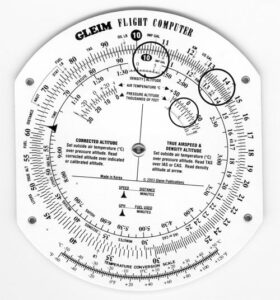
Determining True Airspeed and Density Altitude

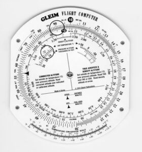
True airspeed and density altitude can be calculated on the calculator side of your flight computer.

Rotate the inner scale until the numbers on the inner and outer scales match.

  • The window that is between “1:30” and “1:50” on the hour scale is labeled “DENSITY ALTITUDE” and the arrow points to the density altitude.
    • The numbers that rotate through this window are in thousands of feet and range from -10 (or -10,000 ft.) to 45 (or +45,000 ft.).
  • The window on the right side below “2:00” and “2:30” on the hour scale is used to set the OAT (above the window) over the pressure altitude (numbers in the window).
    • The OAT is in 5°C increments from +50°C on the left side to -70°C on the right side.
    • The numbers in the window are in thousands of feet and range from -2 (or -2,000 ft.) to 50 (or 50,000 ft.).

Example: What is the TAS and density altitude if the IAS is 130 kt., OAT is -15°C, and the pressure altitude is 5,000 ft.?

  • Using the inner window on the right side, locate the OAT of -15°C and rotate the disk so the pressure altitude of 5,000 ft. (which is labeled “5” on the scale) is under -15°C, as shown in the figure.
  • In the window labeled “DENSITY ALTITUDE,” read the density altitude of approximately 2,500 ft.
  • Locate the IAS of 130 kt., or “13,” on the inner scale. Without moving the disk, read the TAS on the outer scale opposite the IAS, which is 135 kt.

Use your flight computer to solve these practice problems (answers are located below).

OAT Pressure Altitude IAS/CAS TAS Density Altitude
1. +10°C 4,500 95 kt. ______ ______
2.    0°C 7,000 130 kt. ______ ______
3. -20°C 10,000 150 kt. ______ ______
5. -10°C 9,500 115 kt. ______ ______

Answers to practice problems

  1. 102 kt., 4,900 ft.
  2. 144 kt., 6,800 ft.
  3. 169 kt., 8,100 ft.
  4. 131 kt., 8,900 ft.

Corrected (Approximately True) Altitude

Because temperature affects air density, variations in temperature will affect the indications of the altimeter.

  • True altitude is the actual altitude of the airplane above mean sea level (MSL).
  • Indicated altitude is the altitude read directly from the altimeter after it is set to the current altimeter setting.
  • Corrected (approximately true) altitude is found by correcting indicated altitude for nonstandard temperature and pressure.
    • Corrected altitude is indicated altitude corrected for OAT. The term corrected (or approximately true) altitude is used since the indicated OAT does not necessarily reflect the average temperature of the column of air between the airplane and the surface.

Determining Corrected (Approximately True) Altitude

  1. Rotate the inner scale until the numbers on the inner and outer scale match.
  2. The window on the left side below “1:10” and “1:20” on the hour scale is used for calculating corrected altitude.
    • OAT is read through the window at 5°C increments from -60°C to +50C.
    • Pressure altitude, in thousands of feet, is below the window on the movable disk and is in 2,000-ft. increments ranging from 30,000 ft. to -1,000 ft.
  3. The inner scale is labeled “IND ALT,” which means indicated altitude.
    • The outer scale is labeled “TRUE ALT,” which means true (corrected) altitude.
    • These labels are located between “50” and “55” on the appropriate scale.

Example: What is the corrected (or approximately true) altitude if the OAT is -15C, pressure altitude is 8,000 ft., and the indicated altitude is 9,500 ft.?

  • Set OAT of -15°C opposite pressure altitude of 8,000 ft. in the CORRECTED ALTITUDE window, as shown in the figure.
  • Locate the indicated altitude of 9,500 ft., or “95,” on the inner scale; over this value on the outer scale is the corrected (or approximately true) altitude of 9,000 ft.
  • Find corrected (approximately true) altitude.

Use your flight computer to solve these practice problems (answers are below).


OAT Pressure Altitude Indicated Altitude Corrected Altitude
1.  -15°C 9,000 ft. 9,500 ft. ______
2.  +10°C 3,500 ft. 3,000 ft. ______
3.  +20°C 9,000 ft. 10,500 ft. ______
4.  0°C 2,000 ft. 2,500 ft. ______

Answers to practice problems

  1. 9,100 ft.
  2. 3,000 ft.
  3. 11,400 ft.
  4. 2,400 ft.

Off-Course Correction

When your airplane drifts off course due to a wind shift, an inaccurate winds aloft forecast, or a navigation error on your part, your flight computer can be used to determine how many degrees you must turn to parallel your intended course and how many degrees you must turn to converge on your intended course. To calculate this, you must know your present position and

  • Distance you have flown from your departure
  • Distance off course
  • Distance to your destination

Example: You determine you are 11 NM off course when 141 NM from your departure point. If 71 NM remains to be flown, what heading correction is needed to converge on your destination?

  1. First, set the distance off course, 11, on the outer scale opposite the distance you have flown from your departure, 141, on the inner scale.
    • Above the Index, read 4.7°. This is the correction needed to parallel your intended course.
  2. Next, set the distance off course, 11, on the outer scale opposite the distance to your destination, 71, on the inner scale.
    • Above the Index, read 9.3° to converge.
  3. Finally, add the 4.7° to parallel your intended course and the additional 9.3° to converge for a total of 14°.
    • Thus, if you are 11 NM off course and have 71 NM to your destination, you must turn 14° toward your intended course to rejoin your intended course at your destination.

Find off-course correction.

Use your flight computer to solve these practice problems (answers are located below).

Distance from Departure Distance off Course Distance to Destination Total Correction to Converge
1. 150 NM 8 NM 160 NM ______
2. 240 NM 25 NM 100 NM ______
3. 60 NM 10 NM 40 NM ______
4. 100 NM 15 NM 150 NM ______

Answers to practice problems

  1. 6.2°
  2. 21.3°
  3. 25.0°
  4. 15.0°

Radius of Action

Radius of action is the maximum time or distance that an airplane may be flown on a specific course and be able to return to the starting point within a given time.

  • The amount of fuel available, not including reserve fuel, is the determining factor.

Example: You have determined that the groundspeed for the outbound leg is 150 kt. and that the groundspeed for the inbound leg is 120 kt. Fuel available, not including reserve, is 4 hr. What is your radius of action?

  1. First, add the groundspeeds together for a sum of 270 (150 + 120).
  2. Rotate the inner scale so that the total time of 4 hr., or 240 min., is opposite the sum of the groundspeeds, 270, on the outer scale.
  3. Without rotating the disk, locate the groundspeed for the inbound leg of 120 kt. Look directly under 120 to determine a time of 107 min., or 1 hr. 47 min.
    • You may fly outbound for this amount of time before you must turn to return to the departure point.
  4. Without rotating the disk, locate the outbound groundspeed of 150 kt. to determine a time of 133 min., or 2 hr. 13 min.
    • The outbound time of 107 min. plus the inbound time of 133 min. equals 240 min., or 4 hr. (107 + 133).
    • This is equal to the 4 hr. of fuel available.
  5. Place the Index opposite the outbound groundspeed of 150 kt. Locate 107 min. on the inner scale; directly above on the outer scale read 268 NM.
    • The radius of action is 268 NM.

Other Conversions

Converting U.S. Gallons to Imperial Gallons

  1. Near “11” on each scale is an arrow labeled “IMP GAL” (imperial gallon), and near “13” is an arrow labeled “US GAL.”
  2. The imperial gallon is used in Canada and is equivalent to about 1.2 U.S. gallons.
  3. To convert U.S. to imperial gallons or vice-versa, place the arrow labeled “IMP GAL” on one scale opposite “US GAL” on the other scale.
    • Imperial gallons are read on the same scale as the “IMP GAL” arrow, and U.S. gallons are read on the same scale as “US GAL.”
  4. Example: 35 imperial gallons is equivalent to how many U.S. gallons?
    • Rotate the inner scale so the arrow labeled “US GAL” on the inner scale is opposite “IMP GAL” on the outer scale.
  5. Locate 35 imperial gallons on the outer scale. Opposite 35 is 42 on the inner scale.
    • 35 imperial gallons is equivalent to 42 U.S. gallons.

Converting Fuel and Oil Weight

  1. Aviation gas (fuel) weighs 6 lb./U.S. gal., and oil weighs 7.5 lb./U.S. gal. (or 4 qt.).
  2. At “76.8” on the outer scale is an arrow labeled “FUEL LB,” and at “96” on the outer scale is an arrow labeled “OIL LB.”
    • Use these arrows in conjunction with the appropriate “IMP GAL” or “US GAL” arrow on the inner scale.
  3. Example: Determine the weight of 35 U.S. gal. of fuel.
    • Rotate the inner scale so the arrow labeled “US GAL” on the inner scale is opposite the arrow labeled “FUEL LB” on the outer scale.
    • Locate 35 on the inner scale and directly above read 210 on the outer scale.
    • 35 U.S. gal. weigh 210 lb.
  4. Example: Determine the weight of 8 qt. (2 U.S. gal.) of oil.
    1. Rotate the inner scale so that the arrow labeled “US GAL” on the inner scale is opposite the arrow labeled “OIL LB” on the outer scale.
    2. Locate 2 on the inner scale and directly above read 15 on the outer scale.
    3. 8 qt. (or 2 U.S. gal.) of oil weigh 15 lb.

Converting Feet to Meters, Pounds to Kilograms, and Gallons to Liters

  1. A similar process, as previously discussed, can be used to convert feet to meters, pounds to kilograms, gallons to liters, or vice versa.
    • Set the appropriately labeled arrows opposite each other on the outer and inner scales.
    • Read the values on the scale containing the arrow for the corresponding unit of measure.
  2. Example: Convert 2,300 ft. to meters.
    • Rotate the inner scale so that the arrow labeled “METERS” (located at 43.5) on the inner scale is opposite the arrow labeled “FT” (located at 14.3) on the outer scale.
    • Locate 2,300 on the outer scale and directly below read 700 on the inner scale.
    • 2,300 ft. is approximately 700 meters.

Converting Minutes to Seconds

  1. To convert minutes to seconds, place the Index opposite the number of minutes on the outer scale.
    • Locate the arrow labeled “SECONDS” (located at 36) on the inner scale. Directly above the arrow on the outer scale is the number of seconds.
  2. Example: Convert 1.5 min. to seconds.
    • Rotate the inner scale so that the Index is directly under 1.5 on the outer scale.
    • Locate the arrow labeled “SECONDS”; directly above the arrow is 90 on the outer scale.
    • 1.5 min is equal to 90 sec.

Converting Feet per Nautical Mile to Feet per Minute

  1. Some IFR departure procedures require a minimum climb rate. Due to the widely varying performance characteristics of various aircraft, the FAA states the required climb performance in feet to be gained per nautical mile covered on the ground.
    • Since the vertical speed indicator (VSI) in your airplane is calibrated in feet per minute, you must be able to convert to determine whether your airplane can meet the minimum climb performance.
  2. At some airports with noise abatement procedures, the minimum climb rate may be expressed as feet per nautical mile.
  3. To convert, set the Index opposite the groundspeed on the outer scale.
    • The inner scale will represent the climb rate expressed as feet per nautical mile.
    • The outer scale will represent the climb rate expressed in feet per minute.
  4. Example: With a groundspeed of 90 kt. and a minimum climb requirement of 300 ft. per nautical mile, what is the rate of climb in feet per minute?
    • Rotate the inner scale so that the Index is directly under the groundspeed of 90 on the outer scale.
    • Locate 300 on the inner scale and directly above 300 is 450 on the outer scale.
    • A climb rate of 300 feet per nautical mile with a 90-kt. groundspeed is equivalent to a climb rate of 450 feet per minute.

Converting Mach Number to True Airspeed

  1. Use the following procedure to convert a Mach number to true airspeed.
    • Rotate the inner scale so that “MACH NO. INDEX” appears in the right window. Align the arrow with the known outside air temperature.
    • On the inner scale, locate the Mach number.
    • Directly above the Mach number, read the true airspeed on the outer scale.
  2. Example: With an outside air temperature of +10°C, what is the true airspeed at Mach 0.9?
    • Rotate the inner scale so that the arrow labeled “MACH NO. INDEX” is opposite the OAT of +10°C in the right window.
    • Locate Mach 0.9 on the inner scale.
    • Directly above 0.9 is the true airspeed of 590 kt. on the outer scale.

Temperature Conversions

  1. A temperature conversion scale is provided for your use at the bottom of the calculator side of the flight computer.
    • The top scale is degrees Celsius and the bottom scale is degrees Fahrenheit.
  2. Example: Convert 70°F to Celsius.
    1. Locate 70°F on the bottom scale.
    2. Directly above read 21°C.

The Wind Side of The Gleim Flight Computer

  1. The wind side of the flight computer allows you to determine the effect of wind on the airplane in terms of heading and groundspeed.
    • The wind side consists of a rotating plotting transparency attached to a frame and a sliding card.
      • A compass rose is printed on the outside of the plotting transparency.
        • The transparency allows you to mark on it with a pencil and to see the grid on the sliding card.
        • A small metal rivet called a grommet is located at the center of the plotting transparency.
      • At the top of the frame is a large triangle ( ) in the center called the True Index.
        • A correction scale is shown in degrees left and right of the True Index. This scale can be used when applying the wind correction angle (WCA).
        • NOTE: The instructions regarding how to use the wind side of the Gleim flight computer (found below and at the top of the sliding card on the computer itself) require you to set magnetic values (i.e. wind direction and course) under the True Index. We have retained the name “True Index” (vs. “Magnetic Index”) because this term is the industry standard for flight computers. Do not be concerned about this minor semantic inconsistency.
          • We promote the use of magnetic wind directions and course values because many courses are flown directly to or from VORs. VOR compass roses are oriented to magnetic north; thus, it is possible to obtain the magnetic course to or from a VOR directly from the chart without using a plotter.
    • The grid on the sliding card is a section of a large circle.
      • The vertical converging lines, called wind correction lines, represent degrees left or right of the center line.
        • The wind correction lines are spaced at 2 intervals between the horizontal arcs labeled “30” to “150,” and at 1 intervals above the “150” arc.
      • The horizontal arcs, called speed arcs, are concentric circles around the center of the circle and represent a distance from the center.
        • These arcs are used for speed and are spaced two units (usually knots or miles per hour) apart.
      • At the top of the sliding card are directions on how to use the wind side of the flight computer to determine groundspeed and wind correction angle (WCA).
      • The reverse (or information) side of the sliding card is discussed further on in this document in the section information side of sliding card.

Determining Magnetic Heading and Groundspeed

  1. To determine the magnetic heading and groundspeed you must know
    1. The magnetic course of your planned flight, as plotted on your sectional chart.
      • Magnetic course (MC) is the true course (TC) corrected for magnetic variation
                 +W
        MC = TC     Variation
                 -E
        
      • If the flight is to or from a VOR station, magnetic course is determined from the compass rose surrounding the VOR station on the sectional chart.
    2. True airspeed (TAS) as determined from the performance chart(s) in your airplane’s Pilot’s Operating Handbook (POH).
      • If the POH provides TAS in mph, convert mph to knots.
    3. Wind direction and speed, as obtained from the winds aloft forecast.
      • Wind direction is based on true north, so you must convert to magnetic direction by correcting for magnetic variation.
      • Reference a sectional aeronautical chart to determine magnetic variation at the winds aloft reporting site.
      • Magnetic wind (MW) is the true wind (TW) corrected for magnetic variation.
  2. Be sure that you are using the same units of direction and speed throughout your computations.
    1. Since winds aloft are forecast in knots, you must convert your TAS if it is in mph.
    2. If your course has been determined in magnetic direction (e.g., you are using a VOR radial), you must convert the wind direction to magnetic.
  3. As illustrated below, find magnetic heading and groundspeed given the following conditions:
    Magnetic course 095°
    True airspeed 98 kt.
    Magnetic wind 150° at 20 kt.
    1. Rotate the plotting transparency so the magnetic wind direction of 150° is opposite the True Index.
    2. Move the sliding card so the grommet is over a convenient speed arc, such as 100.
    3. Using the speed arcs, place a dot 20 kt. up from the grommet. This represents the wind speed, also called a wind dot. If the grommet is on the 100-kt. speed arc, the dot should be placed on the centerline at the 120-kt. speed arc.
    4. Rotate the plotting transparency so the magnetic course of 095° is opposite the True Index.
    5. Move the sliding card so the wind dot is on the 98-kt. speed arc, which is the TAS.
    6. The WCA is determined by the wind dot and the wind correction lines. In this example, the wind dot is 10° to the right of the center.
                                 +R
      Magnetic heading (MH) = MC    WCA.
                                 -L
      
      • In this problem, MH = 105° (95 + 10).
    7. Groundspeed is read under the grommet; it is 85 kt. in this example.
    8. Under the given conditions, the magnetic heading is 105° and the groundspeed is 85 kt. 
  4. Find wind correction angle, magnetic heading, and groundspeed.
    1. Use your flight computer to solve these practice problems (answers are located below).
         Direction Speed MC TAS WCA MH Speed
      a.  215° 15 kt. 260° 130 mph __________ __________ ________ kt.
      b.  050° 20 kt. 350° 105 kt. __________ __________ ________ kt.
    2. Answers to practice problems
        WCA MH Groundspeed
      a. 5°L 255° 102 kt.
      b. 10°R 360° 94 kt.

Alternative: E6-B Computer Approach To Magnetic Heading

  1. In the previous section, before computing the WCA and groundspeed (GS) on the wind side of the E6-B computer, we converted
    1. TC to MC
    2. Winds (true) to winds (magnetic)
  2. The ALTERNATIVE METHOD suggested on your E6-B is to use TC and winds (true) on the wind side of your E6-B to compute your true heading (TH) and then convert TH to MH. The advantages of this method are


    1. You convert only one true direction to magnetic, not two.
    2. This is the way it has always been taught.
  3. We suggest converting TC and wind (true) to magnetic because pilot activities are in terms of magnetic headings, courses, runways, radials, bearings, and final approach courses. When flying, you should always think magnetic, not true.
    1. While doing magnetic heading problems, you should visualize yourself flying each problem, e.g., a 270° course with a 300° wind will require a right (270°+) heading and have a headwind component.
  4. On your E6-B, you will find directions such as
    1. Set Wind Direction opposite True Index.
    2. Mark Wind Dot up from Grommet.
    3. Place TC under True Index.
    4. Slide TAS under Wind Dot.
    5. Read GS under Grommet.
    6. Read WCA under Wind Dot.
    7. Complete the problem by use of the formulas.
  5. The formulas given are
    • TH = TC ± WCA (wind correction angle)
    • MH = TH ± magnetic variation (E-, W+)
    • CH = MH ± compass deviation
  6. We understand this ALTERNATIVE approach is widely used. It was developed prior to the VOR system, compass roses, airways, etc., which are all identified in magnetic direction, not true direction. Thus you may use it for textbook exercises, but when flying, think magnetic.

Information Side of Sliding Card

  1. Three boxes provide information.
    1. The first, or top, box is the sequence of information required for filing a flight plan.
    2. The middle box contains the special equipment codes used for item 3. on the flight plan sequence.
    3. The bottom box contains a headwind/crosswind component graph, which is used to determine the headwind and crosswind components of a crosswind on a runway.
      1. The bold lines that converge on zero and are labeled from 0° to 90° represent the angle between the runway and wind direction.
      2. The arcs represent the wind velocity in knots.
      3. EXAMPLE: Determine the headwind and the crosswind components of the wind for a landing on Runway 36 when the wind is 030° at 30 kt.
        1. The angle between the runway (360° or 0°) and the wind (030°) is 30°.
        2. Enter the graph at the 30° line and move down to the wind speed arc of 30 kt.
        3. From this point, move horizontally to the left margin to determine a headwind component of 26 kt.
        4. Return to the point of the 30° angle and 30-kt. speed arc. Now, move vertically down to determine a crosswind component of 15 kt.
        5. Landing in this situation is like having a 15-kt. direct crosswind.
  2. On the side margins of the card are mileage scales for sectional charts.
    1. One side is in nautical miles and the other side is in statute miles.